
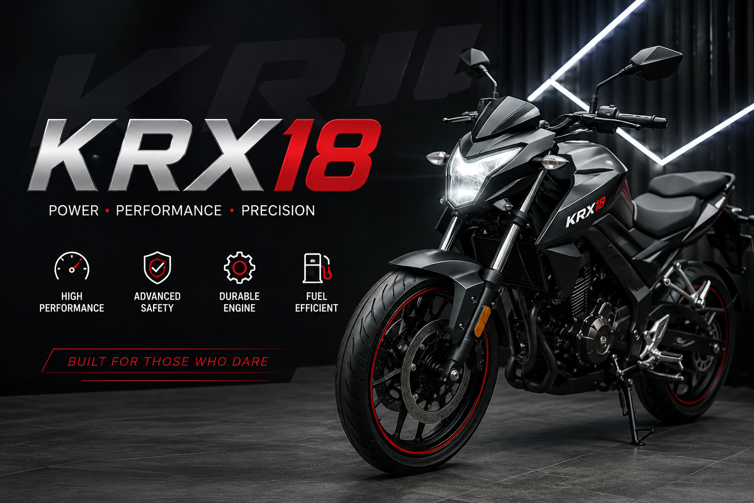

In high-performance acoustic engineering, achieving a balance between explosive dynamic range and distortion-free low-frequency reproduction is one of the most demanding tasks. The KRX18 stands as a benchmark component designed specifically for audio enthusiasts, professional installers, and sound system architects who demand extreme precision at deep frequencies. Built with state-of-the-art materials and an advanced motor structure, this high-output transducer is engineered to redefine bass performance across a wide range of acoustic environments.
Whether integrated into a custom mobile audio build, a dedicated studio monitoring rig, or a high-end sound reinforcement setup, the KRX18 delivers relentless power handling, exceptional transient speed, and effortless low-end extension. Understanding its core architecture, thermal management capabilities, enclosure requirements, and signal processing nuances is essential for unlocking its full potential.
Engineering Overview and Sound Dynamics
At its core, the KRX18 is designed to solve a fundamental physics challenge in loudspeaker design: moving large volumes of air rapidly without introducing structural cone flex or thermal compression. When lower frequencies are driven at high sound pressure levels (SPL), mechanical stress on the cone matrix and thermal energy buildup inside the voice coil can cause sound coloration and efficiency loss.
To mitigate these issues, the mechanical design of the KRX18 focuses on cone rigidity, linear suspension travel, and optimized flux density across the magnetic gap.
+-------------------------------------------------------------------+
|                        KRX18 ACOUSTIC PATHWAY                     |
|                                                                   |
| [Input Signal] --> [Voice Coil / Motor] --> [Rigid Matrix Cone]   |
|                          |                        |               |
|                    (Thermal Vents)          (Linear Travel)       |
|                          v                        v               |
|                  [Heat Dissipation]       [Clean Air Displacement]|
|                          \                        /               |
|                           v                      v                |
|                    [Deep, Impactful Low-Frequency Output]         |
+-------------------------------------------------------------------+
Key Engineering Objectives
- Linearity Under High Excursion: Maintains uniform magnetic flux force over extended physical travel, reducing total harmonic distortion (THD).
- Thermal Endurance: Multi-stage venting routes cool air directly through the motor structure, preventing voice coil overheating during prolonged high-power operation.
- Acoustic Neutrality: The composite cone structure dampens standing waves, ensuring that the sound remains natural, fast, and tight rather than muddy or boomy.
Technical Specifications and Power Handling
To select the right amplifiers, cables, and enclosure materials, reviewing the exact electromechanical parameters of the KRX18 is crucial. These Thiele-Small parameters govern how the unit interacts with air volume inside an enclosure and how it reacts to electrical power from an amplifier.
| Specification Parameter | Value / Measurement | Engineering Function |
| Nominal Diameter | 18 Inches (457 mm) | Surface area (Sd) optimized for maximum displacement |
| Power Handling (RMS) | 1200 Watts | Continuous thermal and mechanical operating threshold |
| Peak Power Handling | 2400 Watts | Short burst capability without mechanical bottoming |
| Nominal Impedance | 4 Ohms / Dual 2 Ohms | Flexible wiring configurations for amplifier matching |
| Frequency Response | 22 Hz – 500 Hz | Deep low-bass coverage extending into upper-bass impact |
| Sensitivity (1W/1m) | 91.5 dB | Converts amplifier power into SPL with high efficiency |
| Voice Coil Diameter | 4.0 Inches (101.6 mm) | High thermal dissipation surface and structural strength |
| Resonant Frequency (Fs) | 27.4 Hz | Low natural resonance for effortless deep bass |
| Equivalent Air Volume (Vas) | 185.0 Liters | Air compliance rating for enclosure sizing |
| Total Q-Factor (Qts) | 0.38 | Ideal balance for ported and bandpass enclosure designs |
| Max Excursion (Xmax) | 22.5 mm (One-Way) | High linear stroke for maximum volume displacement |
Material Science and Structural Features
The performance of any high-power transducer relies heavily on its structural material choices. The KRX18 combines advanced synthetic polymers, structural metals, and rare-earth or high-grade ferrite magnetic compounds to achieve long-term durability.
1. Composite Cone Architecture
The cone matrix utilizes a multi-layer composite weave that pairs ultra-lightweight structural fibers with damping agents. This structure resists cone deformation during extreme air displacement.
- Flex Resistance: Prevents phase cancellation caused by asymmetric cone buckling at extreme volumes.
- Weather Resistance: Protects against humidity and temperature fluctuations in automotive or outdoor installations.
2. High-Temperature Voice Coil
Wound with high-grade copper or aluminum wire over a polyimide/Kapton former, the voice coil tolerates elevated operating temperatures. The adhesive bond remains stable even under continuous high-wattage loads.
3. Die-Cast Aluminum Basket
Instead of stamped steel, the chassis utilizes a heavy-duty die-cast aluminum frame. This provides a rigid platform that prevents mechanical frame flex, shields against stray magnetic interference, and acts as an auxiliary heat sink.
4. High-Roll Surround and Dual Spider Suspension
- High-Roll Surround: Made from treated foam or synthetic rubber, allowing full forward and backward stroke without limiting linear movement.
- Mirrored Dual Spiders: Maintains center alignment of the voice coil inside the tight magnetic gap, eliminating voice coil rub during extreme excursion.
Recommended Enclosure Designs and Calculations
Installing the KRX18 into a improperly designed enclosure will severely limit its output and can lead to premature mechanical failure. Depending on the desired sonic character and physical space constraints, three main enclosure styles are recommended:
                  ENCLOSURE SUITABILITY MATRIX

  [Sealed Enclosure]        [Ported / Vented]       [4th Order Bandpass]
  +------------------+      +------------------+    +------------------+
  | Ultra-compact    |      | Maximum SPL      |    | Extreme Punch    |
  | Tight transient  |      | Deep 30Hz boost  |    | Narrow band      |
  | Flat roll-off    |      | High efficiency  |    | Complex tuning   |
  +------------------+      +------------------+    +------------------+
     Best for SQ              Best for All-Around     Best for Competition
1. Ported / Vented Enclosure (Recommended)
A vented enclosure leverages the back wave of the driver to boost low-end response, making it the most versatile and efficient design for the KRX18.
- Internal Net Volume: 3.5 to 4.5 cubic feet (99 to 127 liters)
- Tuning Frequency ($Fb$): 32 Hz – 35 Hz
- Port Area: Minimum 45 to 60 square inches to prevent port noise (chuffing)
- Sonic Profile: Explosive low-frequency extension, punchy chest impact, and high acoustic efficiency.
2. Sealed Enclosure (Sound Quality Focus)
For listeners prioritizing absolute transient speed, phase coherence, and smooth musical accuracy over raw output level, a sealed alignment is ideal.
- Internal Net Volume: 2.0 to 2.8 cubic feet (56 to 79 liters)
- System Q ($Qtc$): ~0.707 (Critically Damped)
- Sonic Profile: Extremely tight, accurate bass note tracking with smooth low-end roll-off. Highly resistant to physical over-excursion below tuning.
3. 4th-Order Bandpass Enclosure (Maximum Output)
For specialized installations where peak SPL within a focused frequency band is required.
- Sealed Rear Chamber: 1.8 cubic feet
- Vented Front Chamber: 2.5 cubic feet tuned to 48 Hz
- Sonic Profile: Massive acoustic gains over a targeted bandwidth, ideal for high-impact commercial or competition setups.
Acoustic Tuning, DSP Settings, and Crossover Configuration
Even in a perfect cabinet, optimal sound quality depends on precise signal processing. Utilizing a Digital Signal Processor (DSP) or active crossover network ensures clean integration with mid-bass units and main speakers.
Recommended Crossover Configurations
- Subsonic / High-Pass Filter (HPF):
- For Ported Enclosure: Set a 24 dB/octave Butterworth or Linkwitz-Riley HPF at 28 Hz (roughly half an octave below the enclosure tuning frequency). This prevents mechanical damage caused by unloaded over-excursion below port tuning.
- For Sealed Enclosure: Set a 12 dB or 24 dB HPF at 20 Hz to block unwanted infrasonic frequencies.
- Low-Pass Filter (LPF):
- Set a 24 dB/octave Linkwitz-Riley LPF between 60 Hz and 80 Hz.
- Crossing over higher than 80 Hz can pull the acoustic soundstage backward and make localization of bass notes distracting.
Parametric Equalization (EQ) Adjustments
- Cabin / Room Mode Correction: High output around 40 Hz to 50 Hz is common in enclosed spaces. Apply a narrow parametric notch filter (Q = 4.0 to 6.0) to tame standing waves.
- Bottom-End Extension: Apply a gentle low-shelf boost (+2 dB at 30 Hz) if listening in open room environments, provided adequate power headroom is available.
System Integration: Amplification and Electrical Requirements
To drive the KRX18 effectively, the supporting electrical system and amplifier infrastructure must be capable of delivering sustained, stable current.
+-----------------------------------------------------------------------+
|                    ELECTRICAL SUPPLY FLOW CHART                       |
|                                                                       |
| [High-Output Alternator / PSU] --> [Secondary AGM/Lithium Battery]    |
|                                                     |                 |
|                                             [1/0 AWG Power Wire]      |
|                                                     |                 |
|                                                     v                 |
| [KRX18 Transducer] <--- [Dedicated Class-D Amp] <--- [Stiffening Cap] |
+-----------------------------------------------------------------------+
Amplifier Selection Guidelines
- RMS Power Match: Choose an amplifier rated for 1000 W to 1500 W RMS continuous power output into the driver’s final wired impedance.
- Headroom: Operating an amplifier at 70–80% of its max rated capacity prevents signal clipping, which is the leading cause of thermal voice coil failure.
- Amplifier Topology: High-efficiency Class-D mono block amplifiers are strongly recommended due to their low heat output and high current efficiency.
Power Infrastructure Needs
- Power Wire Gauge: Use 1/0 AWG pure oxygen-free copper (OFC) power and ground cables for runs exceeding 10 feet.
- System Capacitance / Battery: Ensure the electrical source can maintain voltage above 12.8V DC under full load. A secondary AGM or Lithium battery placed near the amplifier prevents voltage dips during heavy bass hits.
Comparative Performance Analysis
Evaluating how the KRX18 compares to standard market alternatives highlights its specific strengths in power handling, excursion capabilities, and installation requirements.
| Feature / Metric | Standard 18-Inch Driver | KRX18 Performance Component | Heavy Competition SPL Driver |
| RMS Power Handling | 500W – 800W | 1200W | 2500W – 4000W |
| Transient Response | Moderate / Loose | Fast / Precise | Slow / Heavy |
| Enclosure Requirement | Large (5.0+ cu ft) | Moderate (3.5 cu ft) | Large Heavy Braced Enclosure |
| Sensitivity | 88 dB | 91.5 dB | 84 dB – 86 dB |
| Primary Focus | General Reinforcement | Audiophile SPL & Dynamic Range | Extreme SPL Burst Competitions |
| Recommended Application | Casual Use / Light PA | High-End Mobile / Studio / Custom | Heavy Competition Vehicles |
Step-by-Step Installation and Wiring Guide
Follow this installation workflow to ensure long-term reliability and peak acoustic performance.
+------------------------------------------------------------------+
|                     INSTALLATION WORKFLOW                        |
|                                                                  |
|  Step 1: Verify Enclosure Volume & Port Alignment                |
|  Step 2: Wire Dual Voice Coils (Series or Parallel)              |
|  Step 3: Secure Internal Dampening & Fasten Terminals            |
|  Step 4: Mount Driver with Gaskets and T-Nuts                    |
|  Step 5: Perform Initial Low-Level Signal & Phase Check          |
+------------------------------------------------------------------+
Step 1: Prepare the Enclosure
- Confirm internal net volume matches physical displacement specs (subtract the KRX18 driver displacement of ~0.18 cu ft from internal volume calculations).
- Line internal walls with dense polyfill or acoustic dampening foam to smooth out internal panel reflections.
- Use 3/4-inch or 1-inch high-density MDF or Baltic Birch plywood with internal baffle bracing.
Step 2: Configure Wiring Topologies
Depending on whether your KRX18 features a single or dual voice coil configuration, wire according to your amplifier’s minimum impedance stability rating.
- Parallel Wiring (Dual 2-Ohm Coils to 1-Ohm Load):Connect positive to positive, negative to negative. Ensures maximum power transfer from 1-Ohm stable Class-D amplifiers.
- Series Wiring (Dual 2-Ohm Coils to 4-Ohm Load):Connect coil 1 positive to coil 2 negative. Ideal for bridging multi-channel amplifiers or multi-driver system arrays.
Step 3: Secure Mechanical Mounting
- Pre-drill pilot holes for mounting screws or insert threaded T-nuts to prevent wood splitting.
- Apply a closed-cell foam gasketing tape along the rear flange rim to guarantee an airtight seal against the baffle.
- Hand-tighten mounting bolts in a cross-star pattern to apply even pressure across the aluminum cast frame.
Calibration and Break-In Period
Like any high-performance mechanical assembly, the mechanical suspension (spider and surround) of the KRX18 requires a brief break-in period to reach its nominal Thiele-Small specifications.
Break-In Best Practices
- Initial 20 to 30 Hours: Play moderate-volume dynamic audio content (music with varied acoustic bass or sweeping frequencies) without pushing the driver to its maximum stroke.
- Suspension Settling: During initial play time, the spider fibers soften into their designed mechanical compliance. Resonance frequency ($Fs$) will drop slightly to its steady state, and low-frequency output will gain warmth and depth.
- Final DSP Tuning: Conduct critical acoustic measurements and final EQ tuning after the initial break-in period has concluded.
Maintenance and System Longevity
To preserve output quality and prevent unexpected mechanical failure over years of continuous operation, perform periodic system checks.
Routine Maintenance Checklist
- Fastener Tightness: Vibration over time can loosen mounting screws. Check and snug mounting hardware every six months.
- Visual Surround Inspection: Inspect surround edges for signs of physical wear, UV degradation, or accidental impacts.
- Amplifier Voltage Checks: Measure operating voltage at the amplifier power terminals while driving the system at high volume to ensure electrical supply stability.
- Thermal Monitoring: Feel the center dust cap after extended high-volume listening sessions. Warmth is normal, but excessive heat indicates potential signal clipping or over-driving.
Troubleshooting Common Operational Issues
+-----------------------------------------------------------------------+
|                   TROUBLESHOOTING DECISION TREE                       |
|                                                                       |
|  [Distortion / Rattling]  --> Check Baffle Seal & Clip Lights         |
|  [Lack of Deep Lows]      --> Check Phase Alignment & HPF Settings    |
|  [Amplifier Protect Mode] --> Check Voice Coil DC Resistance (Ohms)   |
+-----------------------------------------------------------------------+
Issue 1: Muddy or Distorted Low-End Output
- Possible Cause: Amplifier clipping, loose enclosure joints, or improper crossover filter settings.
- Solution: Turn down amplifier gain until clip indicators cease flashing. Inspect enclosure seams for air leaks using a smoke test or tactile inspection while playing a 40 Hz test tone.
Issue 2: Weak Bass Impact Inside the Vehicle/Room
- Possible Cause: Phase cancellation between the KRX18 and mid-bass drivers.
- Solution: Toggle the phase setting on your DSP or amplifier between 0° and 180°. Re-evaluate low-frequency level at the primary listening location to confirm phase alignment.
Issue 3: Driver Over-Heating or Burning Smell
- Possible Cause: Severe amplifier signal distortion (clipping) sending DC current to the voice coil.
- Solution: Immediately reduce gain levels. Ensure the subsonic filter is active if using a ported enclosure to prevent uncontrolled low-frequency over-excursion.
Frequently Asked Questions
Can the KRX18 be mounted in an inverted orientation?
Yes, mounting the KRX18 inverted (magnet facing outside the enclosure) is completely viable. Inverted mounting increases net internal box volume slightly and aids in voice coil heat dissipation. Be sure to reverse the electrical wiring polarity (+ to -) at the amplifier to maintain correct acoustic phase alignment with the rest of your audio system.
What is the ideal amplifier dampening factor for this driver?
A high dampening factor (greater than 200 at 4 Ohms) ensures tight control over the heavy cone assembly, particularly when the signal stops abruptly. This prevents overhang or “ringing,” producing clean, defined bass notes.
How does port size affect mechanical noise?
If the port internal cross-sectional area is too small, air velocity inside the duct exceeds 30 meters per second. This creates turbulence, resulting in high-pitched huffing or chuffing noises that obscure clean low frequencies. Always maintain adequate port surface area based on the driver’s total displacement ($Xmax \times Sd$).
Is it safe to run two KRX18 units in a single shared enclosure?
Running multiple units in a single enclosure works exceptionally well. Simply double the required net internal volume and port surface area compared to a single-driver specification. Ensure both units are wired in phase to prevent internal pressure cancellation.
The KRX18 represents a ultimate synthesis of structural endurance, acoustic sensitivity, and sub-bass engineering. By pairing this component with an accurately built enclosure, adequate clean power, and refined signal processing, you create an uncompromising audio foundation capable of reproducing low-frequency content with unmatched authority and realism.
